


ESD Association Advisory – Glossary of Terms
ESD ADV1.0-2009
Revision of ESD ADV1.0-2004
for Electrostatic Discharge Terminology
Glossary – Source www.esda.org
CAUTION NOTICE
Electrostatic Discharge Association (ESDA) standards and publications are designed to serve the public interest by eliminating misunderstandings between manufacturers and purchasers, facilitating the interchangeability and improvement of products and assisting the purchaser in selecting and obtaining the proper product for his particular needs. The existence of such standards and publications shall not in any respect preclude any member or non member of the Association from manufacturing or selling products not conforming to such standards and publications. Nor shall the fact that a standard or publication is published by the association preclude its voluntary use by non members of the Association whether the document is to be used either domestically or internationally. Recommended standards and publications are adopted by the ESDA in accordance with the ANSI Patent policy.
Interpretation of ESDA Standards: The interpretation of standards in-so-far as it may relate to a specific product or manufacturer is a proper matter for the individual company concerned and cannot be undertaken by any person acting for the ESDA. The ESDA Standards Chairman may make comments limited to an explanation or clarification of the technical language or provisions in a standard, but not related to its application to specific products and manufactures. No other person is authorized to comment on behalf of ESDA or any ESDA Standard.
DISCLAIMER OF WARRANTIES
THE CONTENTS OF ESDA’S STANDARDS AND PUBLICATIONS ARE PROVIDED “AS-IS”, AND ESDA MAKES NO REPRESENTATIONS OR WARRANTIES, EXPRESS OR IMPLIED, OF ANY KIND WITH RESPECT TO SUCH CONTENTS. ESDA DISCLAIMS ALL REPRESENTATIONS AND WARRANTIES, INCLUDING WITHOUT LIMITATION, WARRANTIES OF MERCHANTABILITY, FITNESS FOR PARTICULAR PURPOSE OR USE, TITLE AND NON-INFRINGEMENT.
DISCLAIMER OF GUARANTEE
ESDA STANDARDS AND PUBLICATIONS ARE CONSIDERED TECHNICALLY SOUND AT THE TIME THEY ARE APPROVED FOR PUBLICATION. THEY ARE NOT A SUBSTITUTE FOR A PRODUCT SELLER’S OR USER’S OWN JUDGEMENT WITH RESPECT TO ANY PARTICULAR PRODUCT DISCUSSED, AND ESDA DOES NOT UNDERTAKE TO GUARANTEE THE PERFORMANCE OF ANY INDIVIDUAL MANUFACTURER’S PRODUCTS BY VIRTUE OF SUCH STANDARDS OR PUBLICATIONS, THUS, ESDA EXPRESSLY DISCLAIMS ANY RESPONSIBILITY FOR DAMAGES ARISING FROM THE USE, APPLICATION OR RELIANCE BY OTHERS ON THE INFORMATION CONTAINED IN THESE STANDARDS OR PUBLICATIONS.
LIMITATION ON ESDA’S LIABILITY
NEITHER THE ESDA, NOR IT’S MEMBERS, OFFICERS, EMPLOYEES OR OTHER REPRESENTATIVES WILL BE LIABLE FOR DAMAGES ARISING OUT OF OR IN CONNECTION WITH THE USE OR MISUSE OF ESDA STANDARDS OR PUBLICATIONS, EVEN IF ADVISED OF THE POSSIBILITY THEREOF. THIS IS A COMPREHENSIVE LIMITATION OF LIABILITY THAT APPLIES TO ALL DAMAGES OF ANY KIND, INCLUDING WITHOUT LIMITATION, LOSS OF DATA, INCOME OR PROFIT, LOSS OF OR DAMAGE TO PROPERTY AND CLAIMS OF THIRD PARTIES.
Published By:
Electrostatic Discharge Association
7900 Turin Road, Bldg. 3
Rome, NY 13440
ESD Association Advisory for Electrostatic Discharge Terminology – Glossary
1.0 PURPOSE
The purpose of this Glossary is to promote correct terminology in the electrical overstress/electrostatic discharge (EOS/ESD) Community.
2.0 SCOPE
This document contains unified definitions and explanations of terminology used in the standards, TR20.20 Handbook, and other documents of the ESD Association. The Glossary compares EOS/ESD industry terminology with the more familiar usages of electrical and electronic terms. Although the Glossary is not intended to be an encyclopedia, in includes historical information (including explanations of obsolete terminology) and clarifies terminology in other EOS/ESD related documents.
3.0 DEFINITIONS
AC Equipment Ground
a) The ground point at which the equipment grounding conductor is bonded to any piece of equipment, at the equipment end of the conductor in a single-phase 120VAC electrical service.
b) The 3rd wire (green/green with yellow strip) terminal of a receptacle.
c) The entire low impedance path (electrically equivalent to the equipment grounding conductor) from a piece of electrical equipment to the neutral bus at the main service equipment.
Acceptance Equipment
An instrument or collection of instruments that meet the criteria of a standard or standard test method and provides a measurement that is repeatable. It may or may not be as accurate as laboratory evaluation equipment. This equipment is typically used to verify materials, devices or procedures under in-use conditions.
Acceptance Testing
Incoming tests to confirm proper marking and electrical functionality. Data are the form of visual inspection and records, and values or pass/fail notification.
Active Components
Semiconductor devices and elements such as transistors and diodes that can change their basic characteristics in a powered electrical circuit, such as amplifiers and rectifiers.
Air Conductivity
The Ability of air to conduct (pass) an electric current under the influence of an electric field.
Air Ions
Molecular clusters of about 10 molecules (water, impurities, etc.) bound by polarization forces to a slightly charged oxygen or nitrogen molecule.
Air Ionizer
A source of charged air molecules (ions).
Amplitude
The value chosen to be specific to the waveform, typically the difference between the baseline and the first peak.
Ankle Strap
See ground strap.
Antistat, Agent
A substance that is part of or topically applied to a material to render the material surface static dissipative or less susceptible to triboelectric charging.
Attenuator
A resistive network with coaxial connectors to reduce the amplitude of a signal by a specified amount.
Automated Handling Equipment (AHE)
Any form of self-sequencing machinery that manipulates or transports product in any form; e.g. wafers, packaged devices, paper, textiles, etc.
Auxiliary Ground
A separate supplemental grounding conductor for use other than general equipment grounding.
Bandwidth
The high frequency limit where the amplitude of a component of system has decreased to 0.77007 (-3dB) of the constant amplitude low frequency response.
Barrier Strip
A device or apparatus that consists of metal stip and connectors or screws that allow termination and connection of wires or conductors from various components of an electrostatic discharge protected workstation.
Bipolar Ionizer
A device that generates both positively and negatively charged ions.
Body Contracting Mechanism (BCM)
The part of the foot grounder that makes electrical contact with the body.
Bond or Bonding
The permanent joining of metallic parts to form an electrically conductive path that will assure electrical continuity and the capacity to safely conduct any current likely to be imposed.
Bonding Conductor
The wire, strap, flange or other electrically conductive mechanical device used to interconnect two otherwise conductive or dissipative items.
Breakaway Force
The force required to disconnect the ground cord from the cuff.
Bus Bar
A metal strip or bar to which several conductors may be bound.
Bypass Capacitor
A capacitor placed between power and ground to provide a more stable power supply voltage by shunting high frequency signals (such as device switching noise) and/or to provide local power storage (to reduce supply voltage variation when device current usage changes).
Cable Discharge Current
A current produced by causing a stored charge to flow in or out of a cable conductor.
Cable Discharge Event
Occurrence of an Electrical Discharge Event (CDE) when the cable is connected to an electrical system or equipment. Examples of sources include Ethernet cables, T1 lines and other communications or data lines.
Charge Decay
The decrease and/or neutralization of a net electrostatic charge.
Charge Induction
The displacement of charge in an isolated conductor when placed in an electric field (for example, from a charged body). Note: Momentary grounding of such a conductor would result in its gaining a net charge.
Charged Device Model (CDM) Electrostatic Discharge (ESD)
An ESD stress model that approximates the discharge event that occurs when a charged component is quickly discharged to another object at a lower electrostatic potential though a signal pin or terminal.
Charged Device Model (CDM) Electrostatic Discharge (ESD) Tester
Equipment that simulates the component level CDM ESD event using the non-socketed test method.
Charged Plate Monitor (CPM)
An instrument used to measure the charge neutralization properties of ionization equipment.
Coaxial Resistive Prove
A resistor (1.0 ohm example) used to measure the CDM discharge current.
Coaxial Transmission Line
A coaxial cable with controlled impedance used for transferring a signal with minimum loss from one point of the system to another.
Cold Healing
The spontaneous recovery, at room temperature, of an item from a parametric change caused by electrostatic discharge.
Cold Workstation
A work area that has items, assemblies, black boxes, or systems which no power is applied.
Common Connection Point
A device or location (less than 1 ohm within itself) where the conductors of two or more ESD technical elements are connected in order to bring the ungrounded ESD technical elements to the same electrical potential through equipotential bonding.
Common Point Ground
A grounded device or location where the conductors of one or more technical elements are bonded.
Compliance (Periodic) Verification
Testing done to indicate that the performance has not changed from initial baseline values to exceed selected limits.
Compliance Verification (Periodic Testing) Equipment
An instrument or collection of instruments that provide an indication of measurement. It may or may not be repeatable or accurate. This equipment is typically used for indications of pass or fail.
Component
An active passive item such as a resistor, diode, transistor, integrated circuit or hybrid circuit.
Component Failure
A condition in which a tested component does not meet one or more specified static or dynamic data sheet parameters.
Component Under Test (CUT)
A passive or active element, device, integrated circuit, module or subsystem being tested. The CUT is intended to become part of a completed system but is not the entire system.
Compressed Gas Ionizer
Ionization devices that can be used to neutralize charged surfaces and/or remove surface particles with pressurized gas. This type of ionizer may be used to ionize the gas within production equipment.
Conductive Flooring Material
A floor material that has a resistance to ground of less than 1.0 x 10⁵ ohms.
Conductive Material, Resistance
A material that has a surface resistance of less than 1 x 10⁴ ohms or a volume resistance of less than 1 x 10⁴ ohms.
Conductive Material, Resistivity
A material that has a surface resistivity less than 1 x 10⁵ ohms/square or a volume resistivity of less than 1 x 10⁴ ohm-cm.
Conductivity
A. The ratio of the current per unit area (current density) to the electric field in a material. Conductivity is expressed in units of siemens/meter.
B. In non-technical usage, the ability to conduct current.
Constant Area and Force Electrode (CAFE)
An electrode designed to be held by a person’s finger, gloved or ungloved, to reproducibly measure resistance from the finger to a counter electrode such as a ground strap worn on the wrist of the same hand. This electrode is suitable for measuring the resistance of a finger wearing a finger cot.
Contact-Mode Discharge
An ESD event initiated within a relay. The relay is connected to the component pin via a probe, and the component is not in a socket.
Contact-Mode, Non-Socketed Discharge
See Constant-Mode Discharge
Corona
The production of positive and negative ions by a very localized high electric field. The field is normally established by applying a high voltage to a conductor in the shape of a sharp point or wire.
Correlation Sample
A representation device used for correlating measured voltages with known applied voltages.
Critical Path Components
Any portion of the AHE within a certain distance of the device path. That distance should be agreed upon between the manufacturer and the end user.
Cuff
The portion of the wrist strap worn on the wrist. The cuff maintains electrical contact with a person’s skin.
Current Limiting Resistance
A resistance value incorporated in series with the wrist strap or foot grounder’s electrical path to ground. This resistance limits electrical current that could pass through the grounding mechanism in the event of inadvertent user contact with electrical potential.
Current Sense Resistor
A resistor, RCS, of less than five ohms which produces a measurable voltage proportional to current through it with an intrinsic rise-time responsive three times faster than the fastest rise-time to be measured. Δv=Δi x Rcs
Current Sensor
A device used to measure the current in a circuit or system. This device could be non-invasive (by sensing the change in magnetic flux lines) or be very low impedance inserted in series (such as the ESD target).
Current Source MEthod
A TLP methodology (sometimes referred to as constant current method) that utilizes a 500 ohm resistor in series with the DUT and measures the voltage and current at the DUT.
Data Sheet Parameters
Static and dynamic component performance data sheet supplied by the component manufacturer or user.
DC Resistance
The ratio of the DC voltage applied to a conductor to the CD current through it.
Decay Rate
The decrease of charge or voltage per unit time.
Decay Time
The time required for an electrostatic potential to be reduced to a given percentage (usually 10%) of its initial value (See Static Decay Test)
Delay Line
A transmission line used to introduce signal delay between two components of a system.
Destructive Damage
Damage where the operating electrical characteristics or parameters are altered and do not recover to the initial conditions prior to stress.
Device
Product being processed by AHE (e.g., in integrated circuit(IC) or a printed circuit (pc) board).
Device Path
The route traveled by a device in an AHE.
Device Under Test
The device to which the Transient Stimulus will be applied.
di/dt
Current derivative: the slope of the tangent at a particular point in time of the current signal.
Dielectric
An insulating material that can sustain an electric field with little current flow.
Dielectric Breakdown Voltage
The electric potential across an insulating material that causes a sudden increase in current through the material of the insulator.
Dielectric Strength
The maximum electric field that a dielectric can sustain.
Discharge Current
A current produced by causing a stored charge to flow out of a component into a conductor from an ESD simulator.
Discharge Time
The time necessary for a voltage (due to an electrostatic charge) to decay from an initial value to some arbitrarily chosen final value.
Discrete Component
An elementary electronic device constructed as a single unit such as a transistor, resistor, capacitor, inductor, diode, etc.
Dissipative Floor Material
Floor material that has a resistance to ground between 1.0 x 10⁶ and 1.0 x 10⁹ ohms.
Dissipative Materials
A material that has a surface resistance greater than or equal to 1 x 10E4 ohms but less than 1 x 10E11 ohms or a volume resistance greater than or equal to 1 x 10E4 ohms but less than 1 x 10E11 ohms.
Dynamic Parameters
Dynamic parameters are those measured with the component in a functioning (operating) condition. These parameters may include, but are not limited to: full functionality, output rise and fall times under a specified load condition, and dynamic current draw.
Dynamic State
Any operational state where the device is functioning according to its design. Typically, inputs, I/O, and output pins are charged as a required to operated the device. In the dynamic state, the supply current should be changing throughout the range of LDDNOM
Earth Grounding Electrode
The metal rod, metal plate, metal pipe, metal mesh, metal underground water pipe, or grounded metal building frame that are bonded to the neutral bus at the main service entrance.
Electric Charge
An absence or excess of electrons.
Electric Field Shielding Materials
A material that has a surface resistance or a volume resistance of less than 1 x 10³.
Electrical Ionizer
A device that creates ions in gases by use of high voltage electrodes.
Electrical Overstress (EOS)
The exposure of an item to a current or voltage beyond its maximum ratings. This exposure may or may not result in a catastrophic failure.
Electrification Period
The average of five (5) electrification times, plus five (5) seconds.
Electrification Time
The time for the resistance measuring instrument to stabilize at the value of the upper resistance range verification fixture.
Electrostatic Charge
Electric charge at rest.
Electrostatic Damage
Change to an item caused by an electrostatic charge that makes it fail to meet one or more specified parameters.
Electrostatic Discharge (ESD)
The rapid, spontaneous transfer of electrostatic charge induced by a high electrostatic field. Note: Usually, the charge flows through a spark between two bodies at different electrostatic potentials as they approach one another. Details of such procedures, such as the rate of the change transfer, are described in specific electrostatic discharge models.
Electrostatic Discharge (ESD) Control
See static control.
Electrostatic Discharge (ESD) Ground
The point, electrodes, bus bar, metal strips, or other system of conductors that form a path from a statically charged person or object to ground.
Electrostatic Discharge (ESD) Protective
A property of materials capable of one or more of the following: reducing the generation of static electricity, dissipating electrostatic discharges over its surface or volume, or providing shielding from ESD or electrostatic fields.
Electrostatic Discharge (ESD) Protective Symbol
The graphics used to identify items that are specifically designed to provide electrostatic discharge protection.
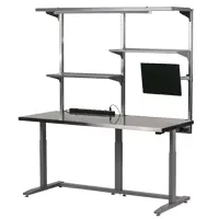
Electrostatic Discharge (ESD) Protective Workstation
An area that is constructed and equipped with the necessary protective materials and equipment to limit damage to electrostatic discharge susceptible items handled therein.
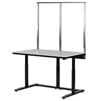
Electrostatic Discharge (ESD) Protective Worksurface
A worksurface that dissipates electrostatic charge from materials placed on the surface or from the surface itself.
Electrostatic Discharge Sensitivity (ESDS)
The ESD level that causes component failure. (Note: see also electrostatic susceptibility).
Electrostatic Discharge (ESD) Shield
A barrier or enclosure that limits the passage of current and attenuates an electromagnetic field resulting from an electrostatic discharge.
Electrostatic Discharge (ESD) Spark Testing
Testing performed with operating equipment or parts to determine their susceptibility to the transient electromagnetic fields produced by an air discharge event.
Electrostatic Discharge Susceptibility (ESDS)
The propensity to be damaged by electrostatic discharge. (See also electrostatic discharge sensitivity).
Electrostatic Discharge Susceptibility (ESDS) Classification
The classification of items according to electrostatic discharge susceptibility voltage ranges. Note: There are various classification methods.
Electrostatic Discharge Susceptibility (ESDS) Symbol
The graphics placed on hardware, assemblies, and documentation for identification of electrostatic discharge susceptible items.
Electrostatic Discharge Susceptible (ESDS) Item
Electrical or electronic piece part, device, component, assembly or equipment item that has some level of electrostatic discharge susceptibility.
Electrostatic Discharge (ESD) Withstand Voltage
The maximum electrostatic discharge (ESD) level that does not cause component failure.
Electrostatic Field
An attractive or repulsive force in space due to the presence of electric charge.
Electrostatic Potential
The voltage difference between a point and an agreed upon difference.
Electrostatic Shield
A barrier or enclosure that limits penetration of an electrostatic field.
Electrostatics
The study of electrostatic charge and its effects.
Emitter
A conducting sharp object, usually a needle or wire, which will cause a corona discharge when kept at a high potential.
Energized
The state of a piece of equipment such that it carries electrical, fluid, thermal, mechanical or other form of energy in a state which could pose a hazard to personnel.
EOS
See electrical overstress.
Equipment Grounding Conductor
The conductor used to connect the noncurrent carrying metal parts of equipment, raceways and other enclosures to the main service equipment ground bus.
Equipotential
Having the same electrical potential; of uniform electrical potential throughout.
ESD
See electrostatic discharge.
ESD Event
Occurrence of a single electrostatic discharge from any source. Examples of source include humans, ESD simulators and other charged objects.
ESD Grounding / Bonding Reference Point
The ESD grounding system selected for use in a facility or situation that best suits the application: a) AC equipment ground; b) auxiliary ground; c) equipotential bonding.
ESD Protected Area (EPA)
A defined location with the necessary materials, tools and equipment capable of controlling static electricity to a level that minimizes damage to ESD susceptible items.
ESD Target
A current transducer used to measure ESD discharges.
ESD Target Adapter
An adapter used to connect reference generators to the ESD target.
ESD Technical Elements
All of the items, materials, devices, tools and equipment used within an EPA for control of static electricity.
ESDS
See Electrostatic Discharge Susceptible
Evaluation Testing
Stringent testing of a wrist strap to determine its electrical and mechanical performance abilities. Data are in the form of values from laboratory testing.
Failure Threshold Current
The supply current value that when exceeded, is considered to have failed the device. To avoid false failures due to change of state it should be greater than the nominal supply current (IDDNOM)
Faraday Cage
A conductive enclosure that attenuates a stationary electrostatic field.
Field Induced Charging
A charging method using electrostatic induction.
Field Plate (FP)
The field plate is a conductive plate used to elevate the potential of the DUT by capacitive coupling.
Final Test Voltage
The voltage on the test plate of the periodic verification instrument at which the discharge time test ends.
Floor Contacting Surfaces
That part of the foot grounder that makes electrical contact to the grounding surface.
Flooring/Foot Grounder System Resistance
The total resistance of the foot grounders when worn by the person standing on a static floor or stainless steel plate.
Foot Grounder
Personnel grounding device worn on the shoe. The device makes electrical contact with the surface on which the wearer is standing. The device also makes contact with the wearer through either direct skin contact or by contacting moisture inside the shoe. This definition includes heel/toe grounders and booties or similar devices (excluding static control shoes).
Foot Grounder System
A foot grounder properly worn by a person where the electrical path includes the person and the foot grounder.
Functional State
The functional state of the device defines the mode in which it is operating.
Functional Testing
End-use testing to confirm electrical functionality. Data is in the form of pass/fail notation or values.
FWHM
Full Width at Half Maximum
Garment System
Any electrically interconnected components of static control apparel.
Ground
a. A conducting connection, whether intentional or accidental between an electrical circuit or equipment and the earth, or to some conducting body that serves in place of the earth.
b. The position or portion of an electrical current at zero potential with respect to the earth.
c. A conducting body, such as the earth or the hull of a steel ship used as a return path for electric currents and as an arbitrary zero reference point.
Ground Cord
The portion of the wrist strap that provides flexibility of movement while completing the electrical circuit between the cuff and the ground.
Ground Current
The current flowing out of the ground pin.
Ground Fault Circuit Interrupter
A device intended for the protection of personnel that functions to de-energize a circuit or portion thereof within an established period of time. It is activated when a current difference between the neutral and hot conductors exceeds some predetermined value that is less than that required to operate the overcurrent protective device of the supply circuit. The current difference is usually caused by a current to ground.
Ground Lead
The portion of the wrist strap, which provides flexibility of movement while completing the electrical circuit between the cuff at one end and a ground system at the other.
Ground Pin
The pin or set of pins that return current to the supply voltage source.
Ground Plane (GP)
A conductive plate used to complete the circuitry for grounding / discharging the DUT.
Ground Reference Point
The prong of the equipment’s ground wire from hand soldering equipment to a workstation ground point. Examples are: (a) the ground U-prong (or round prong) of an AC power cord; (b) the banana plug of a grounding patch cord; (c) the ring or spade lug of a ground jumper wire.
Ground Strap
a. A conductor intended to provide an electrical path to ground.
b. An item used by personnel with a specified resistance, intended to provide a path to ground.
Groundable Point
A designated connection location or assembly used on an electrostatic discharge protective material or device that is intended to accommodate electrical connection from the device to an appropriate electrical ground.
Groundable Point, Floor Material
A point on the floor material that accommodates an electrical connection from the floor material to an appropriate ground.
Groundable Point, Seating
Conductive caster or drag chain used to provide an electrical path from seating to a static control floor or mat.
Groundable Static Control Garment
A garment that exhibits an electrical resistance less than 1 x 10⁹ ohms from point to point and from any point or panel on the garment to the groundable point on the garment.
Groundable Static Control Garment System
Garments that are used to establish the primary ground path for a person shall provide a resistance of less than 35 megohms from the person to the groundable point of the garment. The garment must also meet all the requirements included in the definition for groundable static control garments.
Grounded
Connected to earth or some other conducting body that serves in place of the earth.
Grounded Conductor
A system or circuit conductor that is intentionally grounded.
Grounding Conductor
A conductor used to connect equipment or the ground circuit of a wiring system to a ground electrode or electrodes.
Grounding Electrode Conductor
A conductor used to connect the ground electrode(s) to the equipment grounding conductor, to the grounded conductor, or to both at the main service, at each building or structure where supplied from a common service, or at the source of a separately derived system.
Grounding Resistance
The total resistance from any given point in an electrically conductive path to the grounding electrode.
Hard Ground
A connection to ground through a wire or other conductor that has very little or nearly no resistance (impedance) to ground.
Hardboard (Standard or Tempered)
Heavy sheet material of fibers matted and pressed or rolled to form a strong board.
Horizontal Laminar Flow
Non-turbulent airflow in a horizontal direction.
Hot Work Station
A work area that has items, assemblies, black boxes, or systems which have power applied for testing or repair.
Human Body Model (HBM) Electrostatic Discharge (ESD)
An ESD stress model that approximates the discharge from the fingertips of a typical human being into a pin of a device with another pin grounded.
Human Body Model (HBM) Electrostatic Discharge (ESD) Tester
Equipment that applies human body model electrostatic discharges to a component.
Human Metal Model (HMM) Electrostatic Discharge (ESD) Tester
An ESD stress model that approximates the discharge from a human holding a metal object, such as a screw driver, touching one pin of a device with another pin grounded.
Impedance, Grounded Z
the total opposition (i.e. resistance or reactance) a circuit offers to the flow of alternating current. It is measured in ohms and the lower the ohmic value, the better the quality of the conductor.
Inductive Charging
The transfer of an electric charge to an object when it is momentarily contacted to the ground in the presence of an electric field.
Initial Test Voltage
The voltage on the test plate of the periodic verification instrument at which the discharge time test begins.
Input Protection
Structures, devices or networks connected at the input terminals of an item to prevent electrostatic discharge damage.
Insulated Conductor
A conductor encased within material of composition and thickness that is recognized as electrical insulation.
Insulative Materials
A material that has a surface resistance or a volume resistance equal to or greater than 1 x 10E11 ohms.
Interface Board
The interface board connects the top and bottom 256 pin decks of the tester together to create a single 512 pin test simulator.
In-Use (System) Resistance Test
A system resistance test from a constant area and force electrode, through a glove or finger cot, to a person’s finger or thumb, using a wrist strap as the second electrode.
Ionization
The process by which a neutral atom or molecule acquires a positive or negative charge.
Ionizer
A device which is designed to generate positive and/or negative air ions.
Isolated Conductor
A non-grounded conductor.
Isolated Ground
A separate equipment grounding conductor, which is only bonded to the ground bus (at the main service equipment) and a receptacle. It is permitted to pass through electrical panels, junction boxes, etc., without being bonded to the equipment grounding conductor which services those devices. An isolated ground is not be used to derive an ESD ground.
Isolated Ground Receptacle
A special electrical outlet that contains a separate equipment grounding conductor. The electrical receptacle is usually orange in color and has a colored triangle marked on the face of the receptacle.
Junction Damage
Electrical overstress damage to a semiconductor junction.
Laboratory Evaluation Equipment
An instrument or collection of instruments that meet the criteria of a standard or standard test method that provides a measurement that is accurate and replaceable. This equipment is typically used to qualify materials, devices or procedures prior to acceptance and under controlled conditions.
Laminar Flow Hood Ionization
These devices or systems provide local area ionization coverage in vertical or horizontal laminar flow hoods or benches.
Latch-Up
Latch-Up refers to the activation of parasitic bipolar transistors (junctions) inherent to the CMOS process. These transistors form a latch, which when activated, results in a large and sustained increase in the supply current. This state remains active until power is removed or the device self-destructs. The device is generally non-functional when in this state. Latch-up is typically triggered by an overstress voltage or current on one or more pins.
Latent Failure
A malfunction that occurs following a period of normal operation. NOTE: the failure may be attributable to an earlier electrostatic discharge event. The concept of latent failure is controversial and not totally accepted by all in the technical community.
Level 2 Technical Element
Any ESD technical element that is connected in series to common point ground or to a common connection point through anther technical element.
LP1 and LP2
The peak current measured at the absolute maximum positive and negative of the discharge current waveform.
LPR
The maximum positive peak current value measured using the 500 ohm resistor in the circuit.
LR
The current waveform oscillation in the short circuit waveform is the peak-to-peak ringing that can occur within the first 100ns of Lps MAX.
Machine Model (MM) Electrostatic Discharge (ESD)
An ESD stress model that approximates the discharge to a device pin due to contact of equipment or tools such as those found in the manufacturing line. This model assumes that one pin is contacting the equipment or tool that has an electrostatic charge and another pin is grounded.
Machine Model (MM) Electrostatic Discharge (ESD) Tester
Equipment that applies machine model electrostatic discharges to a component.
Main Bonding Jumper
The connection between the grounded circuit connector and the equipment grounding conductor at the service.
Minority Carrier Flood
Transient stimuli with negative-going voltage component superimposed on the VDD supply
Neutralize
To eliminate an electrostatic field by recombining positive and negative charges, either by conducting the charge to ground or by introducing an equal opposite charge.
New Equipment
Any new or recently purchased HBM testers or simulator test equipment.
No Connect (NC) Pin
A packaging interconnect (pin or ball) that is not bonded to a bond pad.
Nominal Supply Current (LDDNOM)
The range of supply currents possible under all normal operating states.
Non-Contact Mode Discharge
An air discharge ESD event that is initiated by a probe tip approaching a component pin.
Nuclear Ionizer
A device that creates ions usually by alpha emissions which strip electrons from gas molecules to form equal numbers of positive and negative ions in gases.
Offset Voltage
The observed voltage on the isolated conductive plate of a charged plate monitor that has been placed in an ionized environment.
Old Equipment
Any used or older testers or simulator test equipment.
Outlet
a. A receptacle that is connected to a power supply and equipped with a socket for a plug.
b. A point on a wiring system at which current is taken to supply utilization equipment.
Output Protection
Structures, devices or networks connected at the output terminals of an item to prevent electrostatic discharge damage.
Overshoot
As applied to a square wave, is the initial transient response that exceeds the steady-state response.
Oxide Punch-Through
Dielectric breakdown of an oxide layer, as in a semiconductor device.
Passive Components
Elements or single units such as resistors, capacitors and inductors which do not change their basic character when an electrical signal is applied.
Passive Ionizer
A device, usually a sharp grounded needle point, that discharges surfaces in the immediate vicinity by creating a conductive path of air ions.
Peak Current
The highest amplitude of a current waveform.
Peak Offset Voltage
For pulsed ionizers, the maximum value of the offset voltage for each polarity, as the ionizer cycle between positive and negative ion outputs.
Peak Value
The highest amplitude of a waveform.
Periodic Verification
See Compliance (Periodic) Verification
Personnel Charge Accumulation
Charge that accumulates on a person as a result of movement, such as walking across a floor.
Personnel Charge Decay Time
The time required for the voltage on a person to decay from an initial value to some predetermined level under specified conditions through a given floor material and footwear combination.
Personnel Grounding Device
An electrostatic discharge protective device designed to ground any electrostatic charge accumulated on a person. NOTE: The resistance to ground of a personnel-grounding device must be high enough to avoid causing an electrical shock hazard.
Planar Material
An item with a surface sufficiently large and flat to conform to the surface of the electrode(s) used to measure the electrical properties of the material.
Point-to-Point Resistance
The resistance in ohms measured between two electrodes placed on any surface.
Point-to-Point Resistance, Garments
The resistance in ohms measured from one point to another on the surface of the same panel or two different panels of a garment.
Positive Clamp Socket
A zero insertion force (ZIF) socket with a clamping mechanism.
Powered State
A powered state is a state in which all operating power supplies and grounds are supplied to the CUT. For testing purposes, the powered state should be a defined state that would be normal for the final application and in compliance with CUT defined operating parameters. In a powered state, however, there are no signals being supplied to the signal or cock pins.
Preconditioning
The process of changing the input states of a device and applying appropriate electrical signals until a particular desired functional state is achieved.
Pulse Generated Circuit
The circuit network that produces a particular discharge current waveform.
Pulse Width
The time interval between the points on the leading and trailing edges at which the instantaneous value bears a specified relation to the amplitude value of the pulse.
Receptacle
A contact device installed at the outlet for the connection of an attachment plug.
Resistance Range
User-specified upper and lower resistance values which define the user-acceptable resistance values of a wrist strap or wrist strap system.
Resistance to Ground
The resistance in ohms measured between a single electrode placed on a surface and ground.
Resistance to Groundable Point
The resistance in ohms measured between a single electrode placed on a surface and a groundable point.
RF Pin Pairs (RFPP)
Specialized high frequency radio frequency pins that are connected together as a pair of pins.
Ringing
High frequency Oscillation superimposed on the waveform.
Rise Time
The time interval of the leading edge of a pulse between the 10% and 90% points of its amplitude.
Room Ionization
Ionization systems that provide large area coverage with air ions.
Safe Operation Area (SOA)
The current and voltage regime where a device is in normal operation without degradation.
Second Breakdown
A condition where a negative resistance state occurs in a device due to thermal processes. This is designated as the voltage trigger point Vt2 and current It2. This is typically observed after electrical breakdown (e.g. Vt1, It1)
Service Equipment
The necessary equipment, usually consisting of a circuit breaker or switch and fuses, and their accessories, located near the point of entrance of supply conductors to a building or other structure, or an otherwise defined area, and intended to constitute the main control and means of cutoff of the supply.
Settling Time
The time interval between the overshoot peak and the plateau voltage or current value plus 3% of that value.
Short Module
A 14-pin plastic package with all pins internally shorted together, except for pins 1 or 14 depending on the module.
Shorted I/O Pin
This pin is any I/O pin that is metallically connected (1.0 ohms) on the chip or within the package to another I/O pin (or a set of I/O pins).
Shunting Bar
A device that shorts together the terminals of an electrostatic discharge susceptible item forming an equipotential surface.
Signal Pins
Any connected pin that does not supply power to ground in the component.
Sleeve-to-Sleeve Resistance
The resistance in ohms measured from the sleeve opening of the garment to the other sleeve opening of the same garment.
Slew Rate
The maximum rate of change of a voltage signal. It is expressed in units of voltage per unit time.
Socketed Device Model (SDM) Electrostatic Discharge (ESD)
An ESD stress model that approximates the discharge event that occurs as the total charge stored in the test system, consisting of the IC component, socket and test simulator’s parasitic elements, discharges to another object at a lower electrostatic potential (ground), through the test system relay matrix. (This model attempts to duplicate a CDM discharge for a charged component that is in a socket on a test fixture board of a relay based tester.)
Socketed Device Model (SDM) Electrostatic Discharge (ESD) Tester
Equipment that simulates the component level SDM ESD event in a socket.
Socketed Discharge
An ESD event is initiated by a relay. The relay is connected to the component via a single pogo pin and a trace on the test fixture board while the component is placed in a socket.
Spark
An electrical discharge of very short duration, normally between two conductors separated by a gas.
Special Signal Pin Pairs (SSPP)
Some specialized pins are connected together as a pair of pins. For example, XTAL or LVDSOUT 10 pairs are differential type IO pairs.
Spurious Current Pulses
Small machine model (MM) shaped pulses that follow the main pulse and should be less than 15% of lp1 and lpr.
Standard Static Latch-Up
Pulsed injection on signal pins (I-Test) and overvoltage on supply pins.
Static Control
a. Adjective – electrostatic discharge protective.
b. Noun – generic term for measure taken to diminish the effects of electrostatic discharge.
Static Control Floor Material
A permanently installed floor material such as tile, carpet, polymer, epoxy, or sheet flooring that dissipates static charges by grounding personnel, equipment, or other objects contacting the floor material or that controls the generation and accumulation of static charges associated with floor materials.
Static Control Floor Finish
A non-permanent coating periodically applied to existing floor surfaces that dissipates static charges by grounding personnel, equipment or other objects contacting the floor finish or that controls the generation and accumulation of static charges associated with floor materials.
Static Control Floor Mat
A moveable island of material placed over existing flooring that dissipates static charges by grounding personnel, equipment or other objects contacting the floor material or that controls the generation and accumulation of static charges associated with the material.
Static Control Footwear (Other Devices)
Devices (excluding shoes) connected to human feet such as foot straps, toe grounders, booties, or other electro-mechanical connectors, that are intended to control the accumulation of static charge when used in conjunction with a static control floork floor finish, or mat.
Static Control Footwear (Shoes)
Coverings for the human foot that have properties to control the accumulation of static charge when used in conjunction with a static control floor or floor finish, or floor mat.
Static Control Garments
A garment that exhibits an electrical resistance from sleeve-to-sleeve that is less than 1 x 10¹¹ ohms.
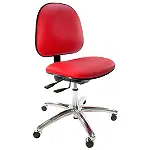
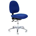
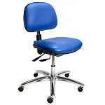
Static Control Seating
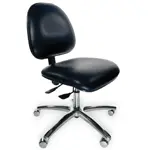
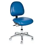
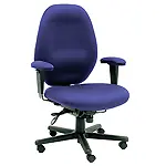
Chairs used in conjunction with a static control floor or static control floor mat that are intended to control the generation, accumulation and dissipation of electrostatic charge associated with seating.
Static Decay Test
A procedure in which an item is first charged to a specific voltage, then allowed to dissipate to a specified voltage while measuring the duration of the charge.
Static Dissipative
A property of a material having a surface resistivity of at least 1 x 10⁵ ohms/square or 1 x 10⁴ ohm-cm volume resistivity but less than 1 x 10¹² ohms/square or 1 x 10¹¹ ohm-cm volume resistivity.
Static Electricity
See electrostatic charge
Static Parameters
Static parameters are those measured with the component in a non-operating condition. These may include, but are not limited to: input breakdown voltage, output high and low voltages, output drive current and supply current.
Static State
Any operational state of the device where no charges are taking place. All outputs, I/O and inputs are unchanging, no internal nodes are switching. In the static state, the supply current should be constant.
Static State – Clocked
Allows some clocks or other internal circuits (like PLL) to operate without outside influence but inputs, I/O and outputs are generally unchanging.
Step Stress Test Hardening
A process whereby a component subjected to increasing electrostatic discharge voltage stress is able to withstand higher stress levels than a similar component stressed at a single lower voltage level.
Step Stress Testing
A test consisting of increasing stress levels applied sequentially to a sample for periods of equal duration.
Strain Relief
A construction feature designed to protect the connections and the cord from premature failure.
Stress Current Limit (ISTRESSMAX)
The negative-going supply stress is progressively stepped by incrementing the voltage amplitude of the 20us pulse, but the current can be independently limited by setting the current limit on the TLU amplifier. A good initial setting for most devices would be 1.50 amperes. If latch-up is not created using this limit, increase this to 3.0 amperes.
Stress Level
The measured quantity of the transient stimulus that is being varied during testing.
Supply Current
The current flowing into the supply pin(s).
Supply/Ground Current (IDD/ISS)
The supply currents are the current flowing into or out of the supply pin(s). Typically, power ground pins are treated as supply pins.
For CMOS devices, the positive supply current is typically called IDD, and the ground current flowing out of the ground is call ISS. For bipolar devices ICC is used for the more positive supply current and IEE for more negative supply current. Sometimes, the ground current is called IGND.
Supply Pin (Set)
A pin or set of pins on the device, which power just one section of the device.
Supply Voltage Source
The DC source that powers the supply pins.
Surface Resistance
The ratio of DC voltage to the current flowing between two electrodes of specified configuration that contact the same side of a material. This measurement is expressed in ohms.
Surface Resistivity
For electric current flowing across a surface, the ratio of DC voltage drop per unit length to the surface current per unit widge. In effect, the surface resistivity is the resistance between two opposite sides of a square and is independent of the size of the square of its dimensional units. Surface resistivity is expressed in ohms/square.
System Characteristics
Signal response of the measurement chain from target or current sensor to the oscilloscope.
Tabletop Ionization
See worksurface ionization.
Target
A current transducer used to measure cable discharge currents flowing into a defined target ground plane.
Target Adapter
An adapter used to connect reference pulse source cables to the current sensor and maintain the 50 ohm coaxial environment for verification of the methodology system.
Target Ground Plane
A flat conductive surface whose potential is used as a common reference.
td
The time duration of the first positive half cycle of the current waveform measured between the first time the current waveform crosses the current axis and the second time the waveform crosses the current axis.
Test Fixture Board (TFB)
The board with a socket mounted on it that electrically connects the socket to the SDM tester.
Test Point
A test point is the location on the test circuit board where the test current is injected. If the stress will be applied with an ESD gun, an ideal test point is a through-plated via into which the contact discharge tip of the ESD gun can be inserted. If the stress will be applied with a 50 ohm IEC source, the test point is a coaxial 50 ohm connector.
Tester Channel Pin
An electrical signal pin built into an ESD simulator that electrically connects the high voltage (HV), ground or floating voltage potentials from the ESD simulator to either a single pin or a group of pins placed on the test fixture board. For example, a 512-pin ESD simulator has 512 tester channel pins.
Tester Channels
The direct communication between the ESD simulator and the pin under test (PUT) is provided by a set of relay signals or wiring paths that transfers the voltages and currents from the simulator to the PUT during the ESD test and measurement sequences.
Thermal Instability
The condition whereby a device is in a negative resistance regime due to thermal processes.
Time Domain Reflectometer (TDR) Method
A TLP methodology that uses an oscilloscope to measure both the incident and the reflected waves from the device under test (DUT).
Time Domain Transmission (TDT) Method
A TLP methodology that uses an oscilloscope to measure the transmitted wave after the device under test (DUT).
Time Domain Transmission and Reflection (TDRT) Method
A TLP methodology that incorporates both the transmitted and reflected waves.
Topical Antistat
An antistat that is applied to the surface of a material for the purpose of making the surface static dissipative or reduce triboelectric charging.
tr
The rise time of the first peak current Ip1 measured between the times 10% and of 90% Ip1.
Transfer Impedance
The measured output voltage from the target divided by a known input current injected into the target.
Transient Pulse Amplitude
The amplitude of the transient stimulus measured in volts (v).
Transient Pulse Width
The time duration that the transient stimulus is present; expressed in units of second (s).
Transient Stimulus
A temporary AC signal superimposed upon the normal DC signal of the supply voltage source.
Transmission Line
A coaxial cable with controlled impedance for transferring a signal with minimum loss from one point of the system to another.
Transmission Line Pulse (TLP)
A rectangular current pulse formed by discharging a charged transmission line cable. In this document, TLP refers to any rectangular pulse source.
Transmission Line Pulse Test System
A test system that applies a rectangular pulse to a device under test and allows measurement of device electrical characteristics during a pulsed state. The system typically measures current and voltage across the device, as well as leakage current after TLP pulse application.
Triboelectric Charging
The generation of electrostatic charges when two materials make contact or are rubbed together, then separated. See also, triboelectric series.
Triboelectric Series
A list of materials arranged so that one can become positively charged when separated from one farther down the list, or negatively charged when separated from one farther up the list. Note: the series’ main utility is to indicate likely resultant charged polarities after triboelectric generation. However, this series is derived from specially prepared and cleaned materials testing in very controlled conditions. In everyday circumstances, materials reasonably close to one another in the series can produce charge polarities opposite to that expected. This series is only a guide.
Trigger
A transient stimulus used to initiate latch up in a device.
Trigger Voltage
The minimum amplitude of the transient pulse.
Tri-State
A pin is in a high impedance state such that it is neither logical low or high.
tz
The duration of the SDM pulse width measured at 75% of lp1.
Unpowered State
In an unpowered state the ground pins are grounded but all power supply and signal pins are left open (floating).
Unprotected Area (UPA)
Any area outside an electrostatic discharge protected area.
VDD MAX (Operating)
This value listed in the device data sheets as the maximum, operating voltage for which the device will still meet all specifications. It is not the same as the absolute maximum voltage allowed without causing permanent damage.
VDD NOMINAL
The typical voltage supplied to the device.
Vector
The digital pattern applied to a group of input pins at one time.
Vector File
A program, or an input file to a program, that contains a list of many vectors used to determine the sequence of the changes required on the input pins to achieve the desired functional state.
Vertical Laminar Flow
Non-turbulent airflow in a vertical direction.
Very Fast Transmission Line Pulse (VF-TLP)
A rectangular current pulse formed by discharging a charged transmission line cable. In this document, VF-TLP refers to any rectangular pulse formed from any pulse source with a fast rise time and short pulse width.
Very Fast Transmission Line Pulse Test System
A test system that applied a rectangular pulse to a device under test and allows measurement of device electrical characteristics during a pulsed state. The system typically measures current and voltage across the device, as well as leakage current after VF-TLP pulse application.
VIH
The voltage that is used to bias a digital input pin to logical High “I”.
VIL
The voltage that is used to bias a digital input pin to logical Low “0”
Voltage Suppression
Reduction of the voltage (V) of a charged object by increasing its capacitance (C) rather than by decreasing its charge (Q), in accordance with the formula V=Q/C. Note: Voltage suppression typically occurs when a charged object is brought closer to ground.
Volume Resistance
The ratio of the DC voltage to current passing between two electrodes, of a specified configuration, that contact opposite sides of the material or object under test. volume resistance is reported in ohms.
Volume Resistivity
The ratio of the DC voltage per unit thickness to the amount of current per unit area passing through a material. Volume resistivity is given in ohm-centimeters.
Worksurface Ionization
Ionization devices or systems used to control static charges at a workstation. Note: This type includes bench top ionizers, overhead worksurface ionizers, and laminar flow hood ionizers.
Worksurface Groundable Point
A point on the Worksurface that is intended to accommodate an electrical connection from the worksurface to an appropriate electrical ground.
Wrist Strap
An assembled device consisting of a wrist cuff and ground cord that provides electrical connection of a person’s skin to ground.
Wrist Strap System
A wrist strap when properly worn by a person, where the electrical path includes the person, the cuff, and the ground cord.
Wunsch-Bell Model
A model for the thermal failure of semiconductor junctions in which the thickness of the junction is assumed to be negligible and the temperature rise is limited by diffusion of heat away from the junction.
Zap (Colloquial Term)
See electrostatic discharge.